Sunday, February 5, 2012

Hydraulic jump

Hydraulic jump


first of all this is a video of the Free Hydraulic jump Experiment I captured it at my faculty of engineering


what is the hydraulic jump

Sudden change in water level, analogous to a shock wave, commonly seen below weirs and sluice gates where a smooth stream of water suddenly rises at a foaming front. The fact that the speed of water waves varies with wavelength and with amplitude leads to a wide variety of effects. Tidal bores, which may be observed on some estuaries, are large-scale examples
or

An abrupt increase of depth in a free-surface liquid flow. A hydraulic jump is characterized by rapid flow and small depths on the upstream side, and by larger depths and smaller velocities on the downstream side. A jump can form only when the upstream flow is supercritical, that is, when the fluid velocity is greater than the propagation velocity c of a small, shallow-water gravity wave (c = gh, where g is the acceleration of gravity and h is the depth). A considerable amount of energy is dissipated in the conversion from supercritical to subcritical flow.

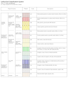
Soil Classification Systems

Soil Classification Systems


Soils Classification Systems

Soil classification systems are used to class soils into groups and subgroups based on their engineering behavior
 Systems use common language to concisely express general characteristics without detailed descriptions

Types

 USDA
 AASHTO
 USCS


USDA Classification

 Complete a grain size analysis of soil
 Determine %G, S, M, C
 Adjust %S, M, C based on gravel content
 Use textural triangle to classify soil
 Use name modifier to account for gravel content

AASHTO Classification

 Developed in 1929 by the Bureau of Public Roads
 Currently uses seven major groups of soils, A1 to A7
 Provides a general rating of the soil as a subgrade for road construction
 Considers grain size distribution and plasticity of fines

Design of beams

Design of beams


Beams are members subjected to simple or double bending the best cross section are S.I.B or B.F.I beams , for bigger spans the plate girder section is used .

Design Considerations

first :Proportioning for strength in bending with due regar of stability of the compression flange and also the adequacy of the selected shape to develop , required strenth in shear .


second : Proportioning for stiffness with due regard to deflections of the member and prevention of excessive deformation under  service condition .

third Proportioning for economy , particularly the selection of a beam size and grade of steel which would lead to an economic design 

The B.F.I. sections have greater lateral stability due to thier wide flange .

The uniform thickness of the flanges facilitates riveting or welding off connections < A type of light beams is the castellated beam , the section modulus of the expanded section is increased

.

Composite Construction

Composite Construction


When a concrete slab is supported by steel beams and there is no provision for shear transfer between the two , the result is a non-composite section .

A great strengthening effect can be obtained by tying the two together to act as a unit in resisting loads steel beams and concrete slabs blind together compositely can often support a 1/3 or even greater increase in load than could steel beams alone in non-composite action.


Advantages of composite Constructions

saving in steel
Increase in the stiffness , smaller deflections
Increased overload capacity of a floor
Reduction of depth of members
saving in fire proofing costs for the beams

The disadvantages for it is the coast of furnishing and installing the shear connectors

Design Of Compression Members

Design Of Compression Members


Choice of Section

If the compression members free to buckle in any direction , the a pipe section would be the most economical since it has the same value of i in all direction .


In order to obtain large values of i , it is desirable to distribute the material in a section as far away from the centroidal axes as possible , in doing so however the thickness of the material should not be reduced below a certain minimum .
By furnishing intermediate supports in a compression member in one direction , the value of the buckling length will differ in two direction , the value of the buckling length will differ in two directions and it might be economical to use sections with different i-values


Design of Tension members Precautions

Design of Tension members Precautions


In axially loaded tension members the stresses are uniformly distributed over the cross section and for a given allowable stress the area of the member can be determined.

In calculating tension members the net area of the section is considered .

to avoid excessive deduction ,the diameter of the rivet must not be too long big , and if there is more than one gauge line , the rivets must be stagger Deduction of one rivet hole only Stagger rivets.


The net area shall be the least than can be determined from any plane cutting the section perpendicularly to its axis diagonally or following a zig-zag line through adjacent rivet holes .

In each case all rivet holes met with shall be deducted from the gross sectional area , where any portion of the sectional area is measured along a diagonal plane , 0.8 only of the net area of such portion shall be taken in computing the effective area with a minimum equal to that obtained by assuming all the holes to be in one perpendicular plane .

Loads And Forces

Loads And Forces


.Dead load
. Live Load for railway bridges
.Live load for road and foot bridges
.Super imposed loads for buildings
.Special live loads
.Dynamic effect on railway bridges
.Dynamic effect on roadway bridges
.Dynamic effect on buildings
.Centrifugal force
. Temperature effect
. Wind Pressure
.Braking forces and traction
.Lateral shock
.Friction resistance of bearings
.Shrinkage of concrete
.Differential settlement
.erection forces
.Fatigue
.Stability and anchorage

Advantages And Disadvantages of Steel Structures

Advantages And Disadvantages of Steel Structures


Advantages

Lightness
 high strengh and stiffness per weight
Ease of fabrication and mass production
fast and easy erection and installation
Substantial elimination of delays due to weather
More accurate detailing
Nonshrinking and noncreeping at ambient temperature
formwork unneeded
Termiteproof and rot proof
Uniform quality
Economy in transportation and handling

Disadvantages

Susceptibility to corrosion
Low fire resistance
Buckling and high deformation due to small sizes of members


Types of steel Structures from structural point of view

Types of steel Structures from structural point of view


Shell Structures
  • Gas holders and tanks for storage of gases
  • Tanks and reservoirs for liquids
  • Bins and Bunkers for loose materials
  • Blast furnaces air heaters and gas scrubbers
  • Pipes
  • Ships hulls annd airplane fuselage

Farmed or Skeletal Structures
  • Industrial buildings
  • Bridges
  • Multi-story buildings , roofs , and domes
  • Hangers
  • Ship yards
  • Railway plates forms
  • Special structures like transmission towers Television masts
  • Oil derricks , cranes ... etc